
Spatial normalization using flirt with diffusion tensor reorientation
Note: This code is no longer maintained. We recommend NIFTI format over Analyze for all data. The reorient program is still available but requires careful validation to ensure that coordinate system conventions are correct with regard to the warp fields and tensors. For DTI registration, try DTI-TK. For multi-modality registration, try ANTs. Both of these programs have the capability to warp and re-orient diffusion tensors using the PPD algorithm [Alexander DC, Pierpaoli C, Basser PJ and Gee JC, Spatial Transformations of Diffusion Tensor Magnetic Resonance Images, IEEE Trans. Medical Imaging, 20(11), 1131-1139, 2001].
On this page... (hide)
1. Overview
This case study shows how to combine FSL's flirt program with Camino's tensor reorientation (using the preservation of principal directions (PPD) algorithm from Alexander et al, IEEE Trans. Medical Imaging 20(11) 1131-1139 2001) to perform spatial normalization of diffusion tensor images. Specifically, we will align two diffusion tensor images from different subjects.
Make sure camino/bin and fsl/bin are in your PATH.
The files Control1.Bfloat and Control3.Bfloat contain the raw diffusion-weighted image data in voxel order. (See the Camino man page or the DTI tutorial for details on standard Camino data formats and how to create them.) First, we shall create background masks for the two images and then use them to create masked diffusion tensor volumes.
2. Making background masks
We shall make background masks using FSL's Brain Extraction Tool (BET). We'll run BET on a single unweighted (b=0) image from each subject. We need analyze format images to input to FSL programs, which the commands below create from the raw Camino format data files:
shredder 0 4 $((4*65)) < Control1.Bfloat > Control1_B0.img
shredder 0 4 $((4*65)) < Control3.Bfloat > Control3_B0.img
analyzeheader -voxeldims 1.7 1.7 2.5 -datadims 128 128 60 -datatype float > Control3_B0.hdr
analyzeheader -voxeldims 1.7 1.7 2.5 -datadims 128 128 60 -datatype float > Control1_B0.hdr
The shredder commands pulls out the first measurements in each voxel, which is a b=0 measurement. Analyze format images consist of a raw data file with name ending .img and a header file with name ending .hdr. The output of the shredder commands provide the raw data files. The Camino command analyzeheader creates appropriate headers. Now we can use BET to create background masks for each subject:
bet2 Control1_B0 Control1 -m
bet2 Control3_B0 Control3 -m
shredder 0 -2 0 < Control1_mask.img > Control1_Mask.Bshort
shredder 0 -2 0 < Control3_mask.img > Control3_Mask.Bshort
The bet2 commands output analyze format files containing one in the foreground portion and zero in the background portion of the image. These mask files store the value in each voxel as a short integer and bet2 outputs data with the native byte ordering. On Linux the native byte ordering is little endian, so we need to switch to big endian for Camino, which is what the shredder commands above do. Now we can use these masks while fitting the diffusion tensor to obtain masked diffusion tensor volumes for each subject:
modelfit -inputfile Control1.Bfloat -inversion 1 -schemefile ION54_6_6_NX.scheme -bgmask Control1_Mask.Bshort > Control1_DT.Bdouble
modelfit -inputfile Control3.Bfloat -inversion 1 -schemefile ION54_6_6_NX.scheme -bgmask Control3_Mask.Bshort > Control3_DT.Bdouble
It is worth checking at this stage that all the principal directions are defined in the same reference frame as the image. Having them in a different reference frame is a common error when handling diffusion MRI data and can lead to unexpectedly poor results. The Tutorials.Tractography? discusses this issue in a bit more detail. Briefly though, running this command:
dteig < Control1_DT.Bdouble | dtpdview -datadims 128 128 60
Should give a result that looks something like this in the axial plane:
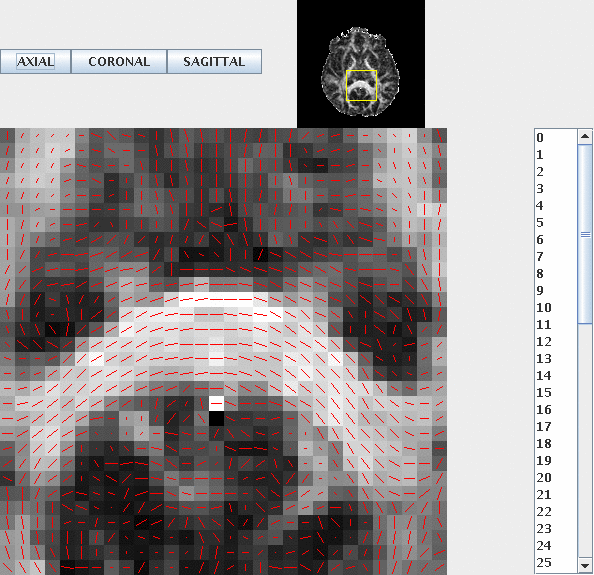
With all the principal directions nicely aligned with the direction of the corpus callosum. It is worth checking the coronal and sagittal planes too.
3. Estimating transformations with registration
To compute the transformation between the two subjects' images, we shall register fractional anisotropy maps from each. First we create fractional anisotropy images in analyze format:
fa < Control1_DT.Bdouble > Control1_FA.Bdouble
mv Control1_FA.Bdouble Control1_FA.img
fa < Control3_DT.Bdouble > Control3_FA.Bdouble
mv Control3_FA.Bdouble Control3_FA.img
analyzeheader -voxeldims 1.7 1.7 2.5 -datadims 128 128 60 -datatype double > Control1_FA.hdr
analyzeheader -voxeldims 1.7 1.7 2.5 -datadims 128 128 60 -datatype double > Control3_FA.hdr
Now we do the registration using flirt:
flirt -in Control1_FA.img -ref Control3_FA.img -out Control1_FA_SN.img -omat C1C3_Affine.txt
The flirt program writes the output to the text file C1C3_Affine.txt. It looks like this:
cat C1C3_Affine.txt
1.0437 0.0346392 -0.0321966 -8.56335
-0.0288245 1.0066 0.151991 -3.35788
0.048813 -0.211909 0.960858 18.6044 0 0 0 1
4. Warping the tensor image
Now we have the transformation, we can transform the tensor image. We'll do it component by component using the flirt program. Here are some shell commands to separate the eight components of the tensor image, convert them to analyze format and warp them using flirt:
for ((i=0; i<8; i=i+1)); do
# Create volume of i-th component
shredder $((i*8)) 8 56 < Control1_DT.Bdouble > Control1_DT_Comp${i}.img
analyzeheader -voxeldims 1.7 1.7 2.5 -datadims 128 128 60 -datatype double > Control1_DT_Comp${i}.hdr
# Transform. Note that the first component contains exit codes, so
# must be transformed using nearest neighbour interpolation.
if [ $i == 0 ]; then
flirt -in Control1_DT_Comp${i}.img -applyxfm -init C1C3_Affine.txt -out Control1_DT_Comp${i}_SN.img -ref Control3_FA.img -interp nearestneighbour
else
flirt -in /tmp/Control1_DT_Comp${i}.img -applyxfm -init C1C3_Affine.txt -out Control1_DT_Comp${i}_SN.img -ref Control3_FA.img
fi
done
The shredder command extracts the i-th component volume. Note that we use nearest-neighbour interpolation for the first component, which contains integer-valued exit codes and trilinear interpolation for all the other components that contain real values.
Now we can recombine the warped component images into a single DT file in camino format. On a linux machine, flirt outputs results with little-endian byte ordering, which we need to reverse, as camino assumes big-endian byte ordering.
cat Control1_DT_Comp?_SN.img | shredder 0 -8 0 | scanner2voxel -voxels 983040 -components 8 -inputdatatype double -outputdatatype double > Control1_DT_SNNR.Bdouble
Finally, we reorient the tensors using PPD:
reorient -trans C1C3_Affine.txt < Control1_DT_SNNR.Bdouble > Control1_DT_SNPPD.Bdouble
Note that reorient will also work with non-linear warps produced by FSL's non-linear registration program fnirt. See the reorient man page for details.